Syncing IMU and Stereo Video: Timestamp Alignment Problems and How to Fix Them

Leela Yanamaddi
November 21, 2026
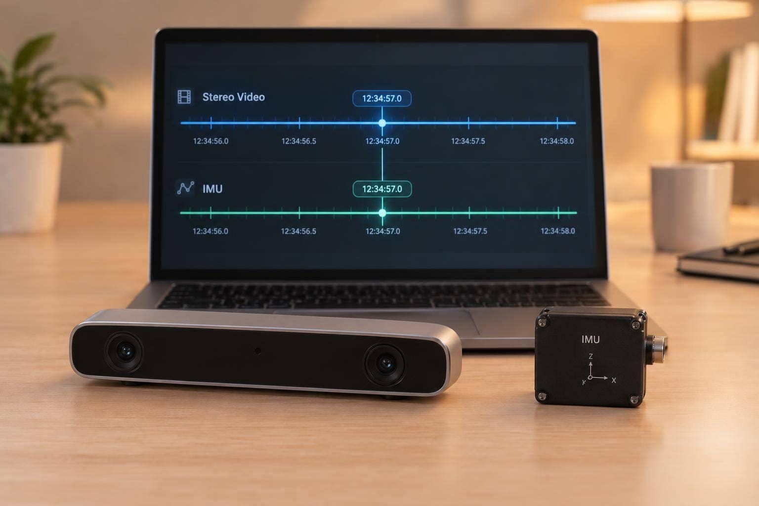
Sync IMU and stereo video using acquisition timestamps on one clock - not packet arrival times. Correct camera–IMU offset and clock drift, then verify that both cameras expose at the same time. At 200 Hz, pairing an image with its nearest IMU sample can add up to 2.5 ms of timing error.
A sound alignment process covers four checks:
- Clock timing: Confirm timestamp units and exposure references before correcting offset or drift.
- Stereo timing: Measure exposure skew, use shared triggers where needed, and account for rolling-shutter row timing.
- IMU coverage: Check for missing samples, then interpolate or preintegrate data at corrected image times without filling gaps.
- Validation: Test on separate motion recordings, set timing limits, and preserve raw data and correction records.
A timestamp shift can fix a steady offset. It cannot recover missing motion data or make mismatched exposures simultaneous.
Correct Camera–IMU Offset, Drift, and Arrival-Time Errors
Identify Offset, Drift, or Buffering
Start with the failure mode indicated by the symptom table: fixed offset, drift, or buffering. Plot camera and IMU capture timestamps against host time. Then plot capture-to-arrival delay over the recording. Use sequence numbers to tell packet loss apart from timing shifts.
| Observed pattern | Most likely cause | Confirmation test | Preferred fix |
|---|---|---|---|
| Stable motion lag | Fixed sensor, trigger, or timestamp-origin offset | Fit offsets independently and check that corrected residuals stay centered | Correct the timestamp relationship or apply a calibrated shift |
| Steadily growing lag | Clock-rate mismatch or drift | Fit offset versus elapsed time and check for a remaining slope after correction | Use a shared clock or periodic synchronization; otherwise, apply a time-varying correction |
| Arrival spikes, stable capture intervals | Queueing, buffering, or packet retransmission | Compare arrival delay with buffer depth, CPU load, and network traffic | Timestamp at acquisition, reduce buffering, and use bounded queues |
| Alignment fluctuates without a trend | Timestamp jitter or uncertain exposure timing | Inspect trigger signals and the spread of residuals | Improve event timestamping and exposure timing |
| Aligned streams, poor fast-motion performance | Wrong exposure timestamp, rolling shutter, or spatial calibration error | Repeat with slow motion and compare reprojection and inertial residuals | Use exposure midpoint or line-time modeling, then validate extrinsics separately |
For delayed or reordered packets, keep the original acquisition timestamp and reorder packets by that timestamp. After changing buffering, check that arrival-delay spikes shrink without changing the acquisition timeline. An unknown capture time represents uncertainty - not a reason to use arrival time instead.
Choose Shared Clocks and Acquisition Timestamps
Use a shared clock - including PTP - only if it timestamps the sensor event rather than the packet. Check whether the IMU timestamp marks sampling or packet assembly after capture.
| Approach | Determinism | Effort | Drift resistance | Fast-motion suitability |
|---|---|---|---|---|
| Software post-processing | Depends on acquisition timestamp quality | Low to moderate | Requires rate correction | Limited by residual jitter |
| Shared clock or PTP | High only when linked to acquisition | Moderate | Good while synchronized | Good with verified event timing |
| Hardware triggers | High for triggered events | Moderate to high | Does not alone align timestamp clocks | Very good with measured latency |
| Shared clock plus triggers | High for events and timestamps | High | High when verified | Strongest option |
Clock-lock status alone does not prove acquisition synchronization.
Estimate Remaining Offset and Drift From Motion
Once timestamps use the right clock, use motion to estimate the remaining error.
- Record varied rotations. Use nonrepeating motion about multiple axes, without blur or tracking loss. Stationary periods and constant-rate spins provide little timing information.
- Estimate the initial offset. Map visual rotation into the gyroscope frame and use cross-correlation. Then refine the estimate with rotation residuals or joint time estimation. Test both offset signs: the correct sign should reduce residuals across several motion segments.
- Fit drift separately. Model the clock relationship as (t_I = a t_C + b), where (b) is the offset and (a - 1) is the relative clock-rate error. Fit windowed offsets, report drift in ppm, and inspect corrected residuals on held-out data. Split the data at clock resets, reconnects, or clear changes in timing behavior. If residuals curve or jump, investigate temperature, buffering, or clock changes before accepting a linear correction.
Visual-Inertial Sensor Calibration -- A Complete Tutorial and Discussion
Align Left and Right Camera Exposures
Once camera–IMU timing is corrected, stereo alignment is the next constraint.
Measure Each Camera’s Exposure Timing
Matching frame numbers does not prove simultaneous exposure. Frame indices show stream order, not exposure time. Pair images by trigger counter or a verified sequence match. Record each camera’s exposure timestamp, exposure duration, sequence number, and clock domain. Then calculate left–right skew as Δt = t_right − t_left, using the same exposure reference for both cameras.
Start with a static, textured scene and a stationary rig. Repeat the test during slow, controlled translation and rotation, then during fast motion. Spatial calibration errors generally remain visible across speeds. Timing errors grow with image motion and may reverse direction when motion reverses.
Stereo skew adds motion-induced displacement to geometric disparity, disrupting matches and depth even when camera–IMU timing is correct. Check static background features first: errors affecting only moving objects do not prove stereo skew.
If frame numbers match but motion artifacts remain, measure the actual exposure windows.
Trigger Both Cameras From the Same Edge
Drive both cameras from one hardware trigger. Check whether the synchronization input controls exposure, frame start, or readout. Measure each camera’s trigger-to-exposure latency and exposure duration using exposure-output signals and an oscilloscope, photodiode, or LED test fixture.
Compare exposure windows, not trigger edges. Calculate each exposure midpoint as: midpoint time = trigger time + latency + half the exposure duration.
Set the skew limit from motion: Δt_max ≈ e_max/(f × ω_max). Here, e_max is the allowed displacement in pixels, f is the focal length in pixels, and ω_max is the maximum angular speed in rad/s. Verify translation accuracy, too. Report the mean, spread, and worst-case skew at the intended frame rate and exposure settings. Retest after configuration changes.
If exposure windows still differ, inspect row timing before changing calibration.
Account for Rolling-Shutter Timing
A shared frame trigger does not expose every row at once. Rolling shutter can therefore still cause mismatches during fast motion. Record the readout direction, line time, exposure duration, image height, and ROI. Use a compatible row-aware model that evaluates IMU motion at the relevant row times.
If errors remain too large, reduce motion, shorten readout, or use synchronized global-shutter hardware. More light can shorten exposure and reduce blur, but it does not remove row timing. A timestamp shift cannot restore scene information captured at incompatible times.
Align IMU Samples to Image Times Without Hiding Gaps
IMU–Camera Timestamp Alignment: Samples, Interpolation, and Gaps
After aligning camera timing, check whether the IMU stream supports those image times.
Check Actual Rates, Gaps, and Timestamp Continuity
Calculate adjacent sample intervals separately for each camera stream and the IMU. Use device timestamps, not host arrival times. Check sequence numbers, duplicate and out-of-order records, clock resets, and timestamp quantization.
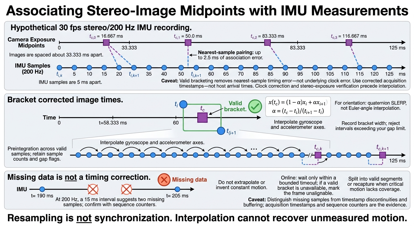
Missing samples and timestamp discontinuities determine whether image-time alignment is valid. At 200 Hz, a 15 ms interval suggests two missing samples; use sequence counters to confirm. Different sample rates are normal, but resampling is not synchronization. Compare capture timestamps with arrival timestamps to spot buffering.
Hypothetical 30 fps stereo/200 Hz IMU recording: Images are spaced about 33.333 ms apart; IMU samples are 5 ms apart. Pairing each image with its nearest IMU sample introduces up to 2.5 ms of association error. Because those periods do not divide evenly, the error changes between frames. Using valid bracketing samples instead removes this nearest-sample timing error, not any underlying clock error.
Interpolate or preintegrate only after confirming that the stream is continuous and correctly timestamped.
Interpolate or Preintegrate IMU Data at Image Times
Use corrected timestamps to bracket each exposure midpoint with IMU samples on both sides. Interpolate each gyroscope and accelerometer axis using:
[ x(t_c) = (1-\alpha)x_i + \alpha x_{i+1}, \qquad \alpha = \frac{t_c-t_i}{t_{i+1}-t_i} ]
Record the bracket width, and reject intervals that exceed your gap limit. For orientation estimates, use quaternion SLERP with consistent quaternion signs - not separate Euler-angle interpolation. Interpolation estimates an intermediate value; it cannot recover unmeasured motion.
After repairing the timeline, use preintegration to handle mismatched sample rates for frame-to-frame motion. Preintegrate all valid IMU samples between consecutive exposure midpoints, including partial boundary intervals. Keep sample counts and gap flags.
Do not extrapolate. During online processing, wait for a missing bracketing sample only within a bounded timeout. If it does not arrive in time, mark the frame as unalignable. Never fill a dropout with invented constant motion.
Decide Whether a Recording Can Be Repaired
Once you have measured the timing error, decide whether to use the recording as-is, split it into segments, or recapture it.
Keep raw files unchanged. Store corrected timestamps, clock mappings, offset and drift estimates, calibration/software versions, and per-frame alignment flags separately.
Re-estimate timing if residuals change over the recording. Do not reuse a clock mapping across a reset without verifying it. Split the recording into valid segments where possible, or recapture it when critical motion lacks coverage. Temporal calibration cannot recover missing samples, resolve ambiguous capture times, stabilize an unreferenced clock, or restore lost rolling-shutter timing.
Conclusion: Validate Timing Before Using the Data
After correction, test the result on motion that wasn’t used for calibration. Treat synchronization checks as the final acceptance test: confirm capture-time definitions, verify offset and drift corrections, check stereo exposures, and validate IMU-to-image associations. If timing stays stable, set quantitative acceptance and logging limits.
Test Motion and Check Remaining Timing Errors
Test corrected timing with slow and fast rotations, translation, and abrupt stops. Compare image motion with gyro traces at the start and end of each recording. Report the maximum or high-percentile residual timing error and start-to-end drift, not just averages. Check left–right exposure agreement and stereo depth consistency across image regions and motion speeds.
Compare reprojection error, trajectory consistency, and failure rates on held-out recordings before and after correction. A single better estimator score doesn’t prove the correction worked. If geometric bias remains, check camera intrinsics, stereo extrinsics, camera–IMU rotation, and rolling-shutter timing before adjusting the offset again.
Set Timing Limits and Preserve Metadata
No universal millisecond threshold exists. Set separate limits for camera–IMU offset, stereo skew, drift, IMU gaps, and interpolation span. Base those limits on angular velocity, linear motion, exposure duration, frame rate, shutter model, stereo baseline, scene depth, and required accuracy. Use Δθ ≈ ωΔt to estimate rotational error, and account for rolling-shutter row timing.
Check that capture timestamps, clock identities and units, exposure references, dropped-data flags, correction versions, and validation results survive transfer, decoding, and processing by downstream systems. Keep this timing metadata so those systems can audit alignment and reproduce results.
FAQs
How often should I recalibrate camera–IMU timing?
Check the camera–IMU extrinsic relationship daily. Even 3–5 mm (about 0.12–0.20 inches) of drift can corrupt precision assembly data. Matching timestamps at startup isn’t enough: clock-rate errors can cause timing offsets to build up over time.
Start every shift with a short calibration check, such as walking a marked path or performing standard rotations. Set your pipelines to automatically flag sessions that exceed your established timing synchronization thresholds.
How can I detect timing errors during live operation?
Plot each stream’s timestamp intervals to check for missing, duplicate, or out-of-order records. Track capture-to-arrival delays: a constant difference points to a fixed offset, a steady slope suggests a clock-rate mismatch, and scattered values indicate transport jitter.
Use stationary recordings as your baseline. Then run motion-based tests, such as angular-velocity cross-correlation, to identify sensor lags. Set up automatic alerts for discontinuities or residual errors that exceed your predefined system timing budget.
How does timing uncertainty affect stereo depth accuracy?
Timing uncertainty reduces stereo depth accuracy when camera timestamps and IMU data are misaligned, pairing image exposures with the wrong motion states. During motion, that timing mismatch creates a spatial disparity error that grows with sensor velocity and timing offset.
Static recordings can hide these errors. Test synchronization during motion to check that jitter stays within task-specific limits for reliable 3D reconstruction.